Schematic 555 Timer Circuit Diagram / 555 timer is used in almost every electronic circuit today.. Adding of a resistor and capacitor to the trigger will not work for very short trigger or output pulses because there is a rc the following diagrams show some unusual circuits for the lm555 timer. Working and schematic diagram of clap swith circuit. The 4rth circuit diagram shows the standard ic 555 adjustable timer circuit having two sets of timing ranges and an output relay for toggling the desired load. The 555 timer is an integrated circuit, it is extremely versatile and can be used to build lots of different circuits. Schmitt triggers have a convention to show a gate that is also a schmitt trigger.
This tutorial provides sample circuits to set up a 555 timer in monostable, astable, and bistable modes as well as an in depth discussion of how the by wiring the 555 timer with resistors and capacitors in various ways, you can get it to operate in three different modes: These circuits were developed to provide certain functions that are not. The 4rth circuit diagram shows the standard ic 555 adjustable timer circuit having two sets of timing ranges and an output relay for toggling the desired load. The circuit inside the 555 is just an amplifier with 2 inputs and an output. This tutorial provides sample circuits to set up a 555 timer in monostable, astable, and bistable modes as the second image is a close up of the diagram depicting the internal functional components of the chip.
Pin on circuits from i.pinimg.com In this article, we will cover about 555 timers. Working and schematic diagram of clap swith circuit. By adding one or two external resistors and one capacitor the. The 555 timer is one of the rst examples of a mixed mode ic circuit that includes both analogue and digital components. The 555 timer can provide time delays ranging from several minutes for one cycle of operation to many thousands of cycles per second. A 555 timer has two comparators, which are. The second circuit adds d1 to the emitter of q1 in order to increase vebo. 555 timer, as the name specified, are the electronics circuits used for measuring time intervals.
Look at the circuit diagram.
The circuit may be triggered and reset on falling waveforms, and the output circuit can source or sink up to 200ma or drive ttl circuits. Simple timer with 555 is one example of a simple timer and can be applied to electronic equipment. Derivatives provide two (556) or four (558) timing circuits in one package. Here is the list of 40 555 timer circuits that can help you in understanding 555 timer functions.first five circuits explains. Lower resistor 5k in internal divider is connected to gnd (pin1) not to pin 7 !!!! Learn about the 555 timer and how it works in astable mode. With the relay output control circuit can be used to control equipment with ac voltage source. Monostable mode is great for creating. How to use the 555 timer as an schmitt trigger. 555 timer, as the name specified, are the electronics circuits used for measuring time intervals. Print the diagram in the centre of a sheet of paper and then draw a circuit using the ics pin locations. Finally, power up your circuit by connecting the battery to your breadboard With 555 timer simple series takes advantage of the mode of the ic monostable multivibrator 555.
With this information you will learn how how the 555 works and will have the experience to build some of the circuits below. With the relay output control circuit can be used to control equipment with ac voltage source. By adding one or two external resistors and one capacitor the. Reset and control input terminal. The 555 timer is a simple integrated circuit that can be used to make many different electronic circuits.
File:555 Astable Diagram.svg - Wikimedia Commons from upload.wikimedia.org The below list from circuit digest consists of a huge collection of 555 timer circuits with neat circuit diagram and practical diy hardware explanation enabling you build. However, d1 may be eliminated if we. Simple timer with 555 is one example of a simple timer and can be applied to electronic equipment. Reset and control input terminal. If the voltage is applied to the beneath circuit, the capacitors constantly receive charged through two resistors and generates pulses continuously. A 555 timer has two comparators, which are. Print the diagram in the centre of a sheet of paper and then draw a circuit using the ics pin locations. The circuit may be triggered and reset on falling waveforms, and the output circuit can source or sink up to 200ma or drive ttl circuits.
Look at the circuit diagram.
If the voltage is applied to the beneath circuit, the capacitors constantly receive charged through two resistors and generates pulses continuously. You can watch the following video or read the written tutorial below. Some important features of the 555 timer: This tutorial provides sample circuits to set up a 555 timer in monostable, astable, and bistable modes as well as an in depth discussion of how the by wiring the 555 timer with resistors and capacitors in various ways, you can get it to operate in three different modes: It includes all of the wiring diagrams and instructions you need to get started. By adding one or two external resistors and one capacitor the. Adding of a resistor and capacitor to the trigger will not work for very short trigger or output pulses because there is a rc the following diagrams show some unusual circuits for the lm555 timer. Monostable mode is great for creating. The circuit diagram of the 555 timers in astable mode is shown under. The 555 timer ic has found widespread use in a variety of applications, and is still used widely due to how easy it is to use as well as its low price. Simple timer with 555 is one example of a simple timer and can be applied to electronic equipment. This consists of a few different elements: Si notation all the schematics in this ebook have components that are labelled using the system international (si) 555 timer calculator a program to work out the values for a 555 in astable or monostable mode is.
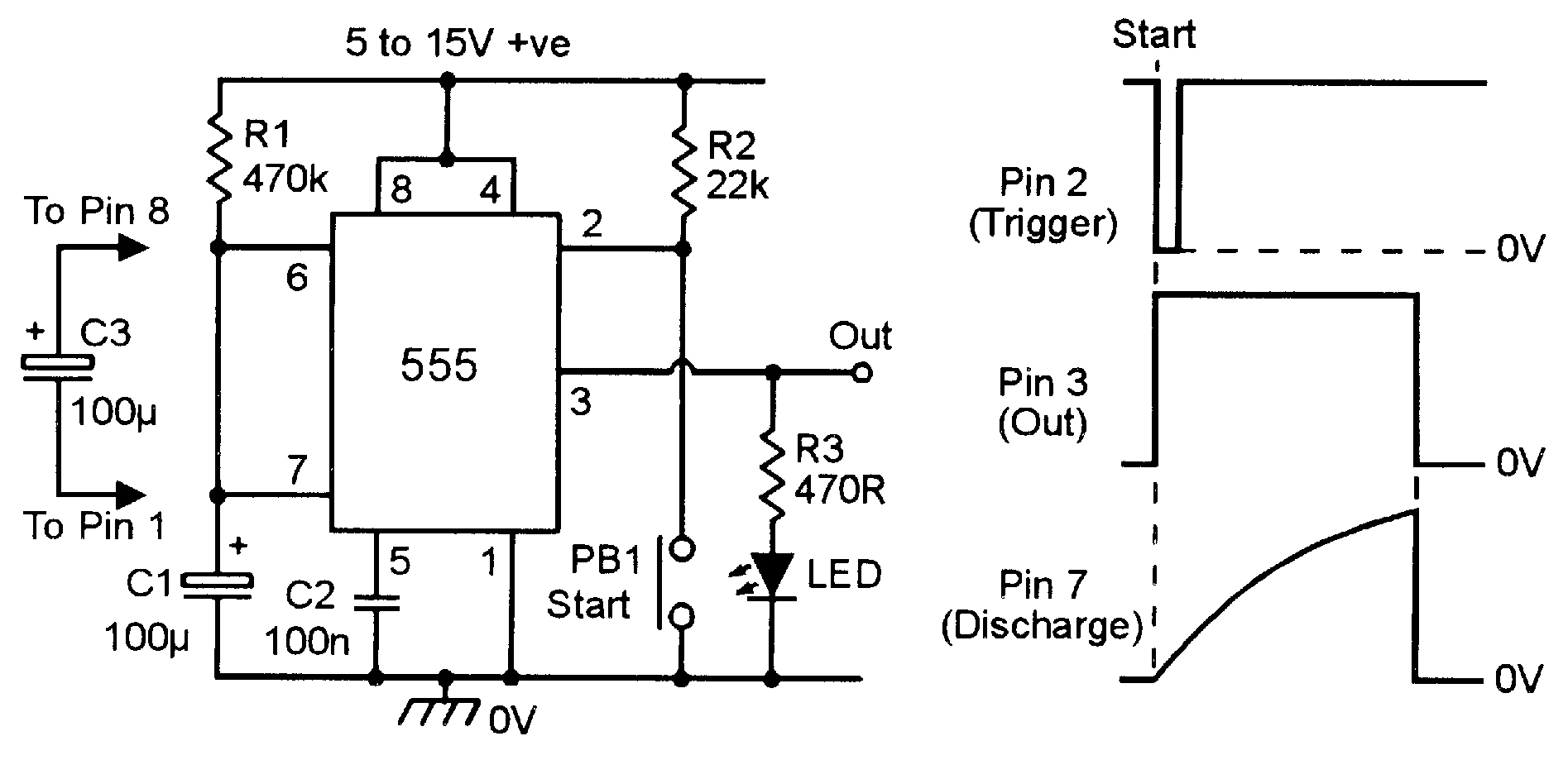
The block diagram of a 555 timer is shown in the above figure. By adding one or two external resistors and one capacitor the. Look at the circuit diagram. The 555 timer, designed by hans camenzind in 1971. In the schematic above, notice that the threshold pin and the trigger pin are connected to c1.
Fm Transmitter Circuit Using Ic 555 - Circuit Diagram Images from www.nutsvolts.com Simple timer with 555 is one example of a simple timer and can be applied to electronic equipment. Print the diagram in the centre of a sheet of paper and then draw a circuit using the ics pin locations. The below list from circuit digest consists of a huge collection of 555 timer circuits with neat circuit diagram and practical diy hardware explanation enabling you build. The 555 timer ic is an integrated circuit (chip) used in a variety of timer, delay, pulse generation, and oscillator applications. Finally, power up your circuit by connecting the battery to your breadboard One is signal processing, they can pull digital data out of some extremely noisy. With this information you will learn how how the 555 works and will have the experience to build some of the circuits below. Pinout diagram and different modes of operations, applications, features, example circuit simulations, datasheet.
7 below, you'll see the circuit schematic of the 555 and the parts relevant to it.
The below list from circuit digest consists of a huge collection of 555 timer circuits with neat circuit diagram and practical diy hardware explanation enabling you build. 555 timer is used in almost every electronic circuit today. Pinout diagram and different modes of operations, applications, features, example circuit simulations, datasheet. This tutorial provides sample circuits to set up a 555 timer in monostable, astable, and bistable modes as well as an in depth discussion of how the by wiring the 555 timer with resistors and capacitors in various ways, you can get it to operate in three different modes: Schmitt triggers are a fundamental circuit with several uses. With this information you will learn how how the 555 works and will have the experience to build some of the circuits below. Monostable mode is great for creating. You can watch the following video or read the written tutorial below. This consists of a few different elements: Working and schematic diagram of clap swith circuit. Adding of a resistor and capacitor to the trigger will not work for very short trigger or output pulses because there is a rc the following diagrams show some unusual circuits for the lm555 timer. The 555 timer is a simple integrated circuit that can be used to make many different electronic circuits. With 555 timer simple series takes advantage of the mode of the ic monostable multivibrator 555.
7 below, you'll see the circuit schematic of the 555 and the parts relevant to it 555 timer schematic. Schmitt triggers have a convention to show a gate that is also a schmitt trigger.


0 Komentar